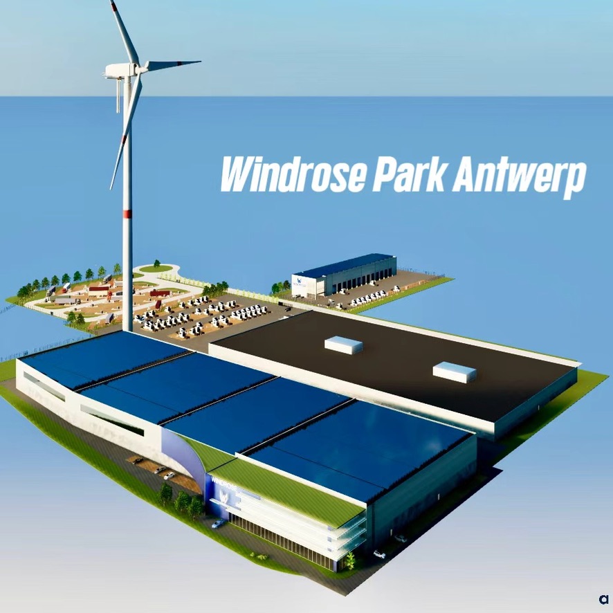
How it works
Wind Farm
⚡ Charges
Power
Ships to site
Site
Through a grid PCS: truck chargers,
site load and grid services
site load and grid services
Windrose Power1.41 MWh1C · 1.4 MW
Inside the Container
Each string is one E700: 4 packs and 705 kWh, with that truck's distribution unit and controller.
| Part | Qty | What it does in the container |
|---|---|---|
| LFP battery pack | 8 | 176.3 kWh, 766 V nominal, 238 cells in series, 2,800 × 1,081 × 269 mm, 1,146 kg. Each pack has its own service disconnect. |
| Power distribution unit | 2 | 600 A main contactor, precharge, insulation monitoring and a 24 V / 6 kW DC-DC converter for each string. |
| Vehicle controller | 2 | Wakes the pack monitors, sequences the contactors, supervises the battery and talks to the PCS. |
| Battery thermal unit | 2 | 12 kW of cooling each, with a high-voltage compressor powered from the battery. |
| Coolant heater | 2 | 12 kW each, one per thermal unit. |
| Coolant pump and filter | 2 | One set per thermal unit. |
| Expansion tank | 1 | 5 L + 5 L, on the highest point of the return line. |
| High- and low-voltage harnesses | — | Truck harness designs, cut to the container's lengths. |
| 24 V battery | 2 | Two in series, as in the truck. |
New for the container: automatic fire suppression with smoke and off-gas detection, DC wall bushings, the container conversion and the pack frame.
Thermal Management
Each pack has its own supply and return branch (DN20) with isolation valves. The branches feed one riser per column (DN25) and a header along the roof (DN32). The two thermal units run in parallel, each with its own pump and heater. The expansion tank sits at the highest point of the return line, and the power distribution units are cooled from the same loop.
Deep Dive
Every string in the container is one truck's battery system, moved into a box: four packs, the power distribution unit, the vehicle controller and the thermal units, with the same part numbers. The specifications below are the truck's, and each one explains a design choice in the container.
The model opens assembled. Explode pulls each part out. Click a part. The card links to that part's model.
The pack is the cell-to-pack LFP unit from the Windrose E700: cells, battery monitor, high-voltage parts and a liquid cold plate in one IP67 enclosure. Four of them make one truck's 705 kWh; four of them make one string here.
| Specification | Value | Why it matters in the container |
|---|---|---|
| Cell | LFP prismatic, 230 Ah, 3.22 V nominal, 2.5–3.65 V, 4.2 kg, 180 Wh/kg | The same cell as the truck, so the container draws on the truck's cell supply and test record instead of a second qualification. |
| Topology | 1P238S: 238 cells in series, no parallel groups | Every cell carries the pack current and is measured on its own. Paralleling happens at string level (four packs) and on the AC side (two strings), never inside a pack. |
| Operating voltage | 595–868.7 V DC (766.4 V nominal) | Sets the window for everything downstream: PDU, cables, the thermal-unit compressor and the PCS DC input all come from, or are chosen for, this range. |
| Energy and mass | 176.3 kWh · 1,146 kg · 155 Wh/kg | Eight packs are 9.2 t and 1.41 MWh in a standard-height 20 ft box, which travels at normal road height without a low-loader. |
| Cycle life | 4,500 full cycles at 25 °C to 70 % state of health (cell: over 6,000) | Stationary duty is daily cycling. 4,500 cycles is more than twelve years at one full cycle per day, provided the cells are kept at the rated temperature. |
| Temperature | Cell charge 0–60 °C, discharge −30–65 °C · pack thermal window −30–60 °C | LFP cannot be charged below 0 °C and ages faster when hot. This is why the container carries both 24 kW of cooling and 24 kW of heating. |
| Inside the pack | Main-negative contactor, fuse, current shunt, service disconnect, cold plate, IP67 | Each pack can be isolated and swapped on its own. Precharge, the main-positive contactor and insulation monitoring are not duplicated eight times; they live once per string in the PDU. |
| Approvals held | UN 38.3 (transport) · UN ECE R100.03 (vehicle battery safety) | Thermal shock and cycling, external short circuit, overcharge, over-discharge, over-temperature, vibration, mechanical shock and fire resistance are already tested at pack level. Those reports are the starting evidence for the container's EU Battery Regulation file. |
The PDU is the truck's high-voltage junction box. It joins the four packs into one bus, switches that bus, watches its insulation and makes the 24 V that runs everything else. In the container its output goes to a DC wall bushing instead of the drive axles.
| Specification | Value | Why it matters in the container |
|---|---|---|
| Pack inputs | Six pack positions, each with its own positive and negative cable; LFP uses four | Each pack has its own path to the bus, so one pack can be disconnected at its service switch while the other three stay in service. |
| Main contactor | 600 A main-positive contactor | The one switch that makes the string live or dead. The packs' own contactors are main-negative only, so both poles open on shutdown. |
| Precharge | 100 Ω resistor; main positive closes once the voltage difference stays below 15 V for 100 ms | The PCS DC link is a large capacitor. Charging it through the resistor first keeps the inrush off the contactor contacts, which is what lets them reach their rated life. |
| Insulation monitoring | Continuous insulation monitor on the high-voltage bus | The bus is a floating 595–869 V system. A drop in insulation to the container body is detected and reported before it becomes a hazard, the same way it is on the truck chassis. |
| 24 V supply | 24 V / 6 kW DC-DC converter fed from the pack bus; two 12 V batteries for wake-up | Controllers, pumps, detection and the thermal-unit fans run from the battery itself. The container needs no external auxiliary supply. |
| Live and dead zones | Packs to PDU inputs: always live · after the PDU contactors: dead on shutdown | The service rule is identical to the truck's. Only the pack service disconnects make the input side safe. |
| Cooling | Liquid-cooled from the pack loop | Contactors and the DC-DC converter run at coolant temperature, not at the air temperature inside a closed steel box. |
| Shutdown and emergency stop | Normal: PCS ramps below 5 A, then the contactors open in reverse order · E-stop and fire detection: both PDUs open at once | Opening a contactor under load shortens its life. The sequence protects it; the emergency path ignores the sequence. |
Without the truck PDU, the PCS would need its own precharge circuit, a DC combiner cabinet, a separate 24 V supply and a separate high-voltage feed for the thermal units.
The controller is the truck's vehicle controller with one configuration word changed. It talks to the four pack monitors over CAN, drives the PDU, runs the thermal units and tells the PCS how much current it may draw or push.
| Specification | Value | Why it matters in the container |
|---|---|---|
| Hardware and software | Truck vehicle controller, unchanged; storage mode selected by configuration | The contactor sequencing, insulation check, thermal-management control and fault diagnosis are the functions already in service on the truck. One spare part and one diagnostic tool cover both products. |
| Battery data | Cell voltages, temperatures, state of charge and state of health from each pack's own monitor over CAN | The pack monitor is the source of truth for the cells; the controller supervises four of them and sets the limits. The EU Battery Regulation's read-only state-of-health access (Art. 14) will be served from here. |
| Interface to the PCS | Charge and discharge current limits, released after power-up and withdrawn before shutdown | The PCS never decides on its own how hard to drive the battery. The limits follow cell temperature and state of charge, exactly as they do for the truck's charger. |
| Strings | Two independent controllers; strings are paralleled only on the AC side | A fault on one string takes 705 kWh offline, not 1.41 MWh. No DC paralleling means no circulating current between strings at different states of charge. |
21271102127210130711021270131311110
The 1.4 MW rating exists only inside a cell temperature window. The battery monitor's charge map allows the full 1C between 20 and 35 °C, reduces it at 5–15 °C and at 40–45 °C, and allows no charging at all below 5 °C. The thermal units are what keep the packs in that window, so they are sized and powered like the truck's.
| Specification | Value | Why it matters in the container |
|---|---|---|
| Cooling need | About 12 kW for eight packs at 1C (truck design point: 6 kW for four packs at 1.08C) | Two 12 kW units run in parallel. Either unit alone covers the 1C cooling need; the second is the margin. |
| Heating need | About 14 kW for eight packs; 2 × 12 kW coolant heaters installed | Below 5 °C the packs can only be heated. The heaters bring them into the charge window; the truck's figure is 19 °C per hour from −20 °C ambient. |
| Thermal unit | Truck battery thermal unit: 12 kW refrigeration, high-voltage compressor rated 540–930 V on the pack bus, own pump, filter and 12 kW heater | The compressor runs from the battery, so cooling is available whenever the string is live and needs no site supply. The 540–930 V rating covers the whole 595–869 V pack range. |
| Hot-weather proof | Truck test, 20–80 % at 1C: 38.5 min with max cell 42 °C at 25 °C ambient; 48 min with max cell 45 °C at 45 °C ambient | The same cold plate and thermal unit hold the cells inside the window at full rate even at 45 °C ambient. In the container the duty is the same 1C on the same packs. |
| Loop layout | Per pack: DN20 supply and return with isolation valves · per column: DN25 riser · roof header DN32 · 5 L + 5 L expansion tank at the highest point of the return | A pack can be valved off and swapped without draining the loop. The header and risers give every pack the same flow path so no pack runs warmer than its neighbours. |
| What is cooled | Every pack's cold plate, then the PDU, on one loop | One coolant, one set of pumps, one expansion tank. The electronics never see the air temperature inside the box. |
| Cycle life link | 4,500 cycles is rated at 25 °C | The warranty-relevant life figure assumes the thermal system does its job. Cooling is not an accessory; it is what makes the cycle rating real. |
| Part | On the E700 | In the container | What changes |
|---|---|---|---|
| LFP battery pack2101100 | 4 | 8 | Nothing. Same part, same approvals; racked two columns by four layers instead of under a frame. |
| Power distribution unit2104100 | 1 | 2 | Nothing inside. The output cable runs to a DC wall bushing instead of the drive axles. |
| Vehicle controller2108100 | 1 | 2 | One configuration word: storage mode. Hardware and firmware unchanged. |
| Thermal unit, heater, pump, filter2127110212721013071102127013 | 2 | 2 | Nothing. The truck also carries two units for 24 kW of cooling. |
| Expansion tank1311110 | 1 | 1 | Nothing; mounted at the highest point of the return line. |
| High- and low-voltage harnesses | — | — | Same cable and connector designs, cut to container lengths; 185 mm² from each PDU to the bushing. |
| 24 V batteries3703100 | 2 | 2 | Nothing; two 12 V in series, charged by the PDU. |
| New for the container | — | — | Automatic fire suppression with smoke and off-gas detection, deflagration vents, DC wall bushings, the welded pack frame and the container conversion. |
Rule behind the design: if the truck already has a part for the job, the container uses that part.
Certification
| Scope | Standard | Status |
|---|---|---|
| Battery pack — transport | UN 38.3 | Held |
| Battery pack — vehicle safety | UN ECE R100.03 — E24*100R03/02*0309*00 | Held |
| Container — EU Battery Regulation | (EU) 2023/1542: Annex V stationary storage safety, CE marking | In preparation |
| Stationary storage safety | EN IEC 62619 · IEC 62933-5-2 | In preparation |
| Large-scale fire test | UL 9540A, unit level | Planned |
| Electrical | Low Voltage Directive 2014/35/EU · EMC Directive 2014/30/EU | In preparation |
| Battery data | Performance parameters and read-only state-of-health access (Art. 10, 14); EU battery passport from 18 Feb 2027 | In preparation |
| Transport — whole container | UN 3536, ADR / IMDG special provision 389 — shipped fully assembled at 30–50 % state of charge | Applies |
| Grid connection | Through a PCS on the Synergrid C10/26 list, EN 50549 | PCS supplier |
| Site permit (Flanders) | VLAREM II chapter 6.13 | Per site |
Producer and EU manufacturer: Windrose Technology Antwerp N.V.
Battery Chemistry
Power uses LFP (Lithium Iron Phosphate) — the safest, longest-lived lithium-ion chemistry. Here's how it compares to NCA (Nickel Cobalt Aluminum), used in many stationary storage systems.
Power · Battery Chemistry
LFP
Lithium Iron Phosphate
NCA · Battery Chemistry
NCA
Nickel Cobalt Aluminum
Inside the Battery — LFP vs NCA
Cell Cross-Section — Cathode (+) Top · Anode (−) Bottom
Cathode Crystal Structure — Where the Elements Live
LFP — Olivine Structure
LiFePO₄
Li sits in channels between FePO₄ layers. O is locked inside PO₄ tetrahedra — cannot escape, even above 270 °C.
NCA — Layered Oxide
LiNi₀.₈Co₀.₁₅Al₀.₀₅O₂
Li alternates with Ni/Co/Al-O layers. O is held by weaker ionic bonds — releases above ~150 °C, igniting the electrolyte.
Battery Lifetime: LFP vs NCA
At one full charge/discharge cycle per day, LFP reaches 8,000+ cycles in over 20 years with minimal capacity fade. NCA chemistry degrades faster under heavy daily cycling, typically reaching end-of-life around 8 years. LFP also releases far less heat and gas if a cell fails — a critical safety advantage for outdoor storage.
Specification Sheet
| Category | Item | Parameters |
|---|---|---|
| Battery | Capacity | 1.41 MWh (8 × 176.3 kWh) |
| Cell | LFP, 230 Ah prismatic | |
| Packs | 8 × Windrose truck LFP pack, 238 cells in series | |
| Configuration | 2 strings × 4 packs = 2 × Windrose E700, 705 kWh each | |
| DC Interface | Voltage Range | 595–869 V DC (766 V nominal) |
| Design Rate | 1C continuous (≈ 1.4 MW DC) | |
| Outputs | 2 independent DC strings to the PCS | |
| String Protection | 600 A main contactor, precharge, insulation monitoring | |
| Thermal | Cooling | 2 × 12 kW, liquid |
| Heating | 2 × 12 kW | |
| Auxiliary Power | 24 V from on-board DC-DC, 6 kW per string | |
| Safety | Fire Protection | Automatic suppression, smoke and off-gas detection |
| Service Disconnect | On every pack | |
| Size & Weight | Container | 20 ft standard, not high-cube: 6,058 × 2,438 × 2,591 mm |
| Battery Mass | 9.2 t (8 × 1,146 kg) | |
| Grid | Power Conversion | External PCS (EN 50549, Synergrid C10/26) |
Contact us — we'll size Power for your site, PCS and grid connection.
Contact Windrose →